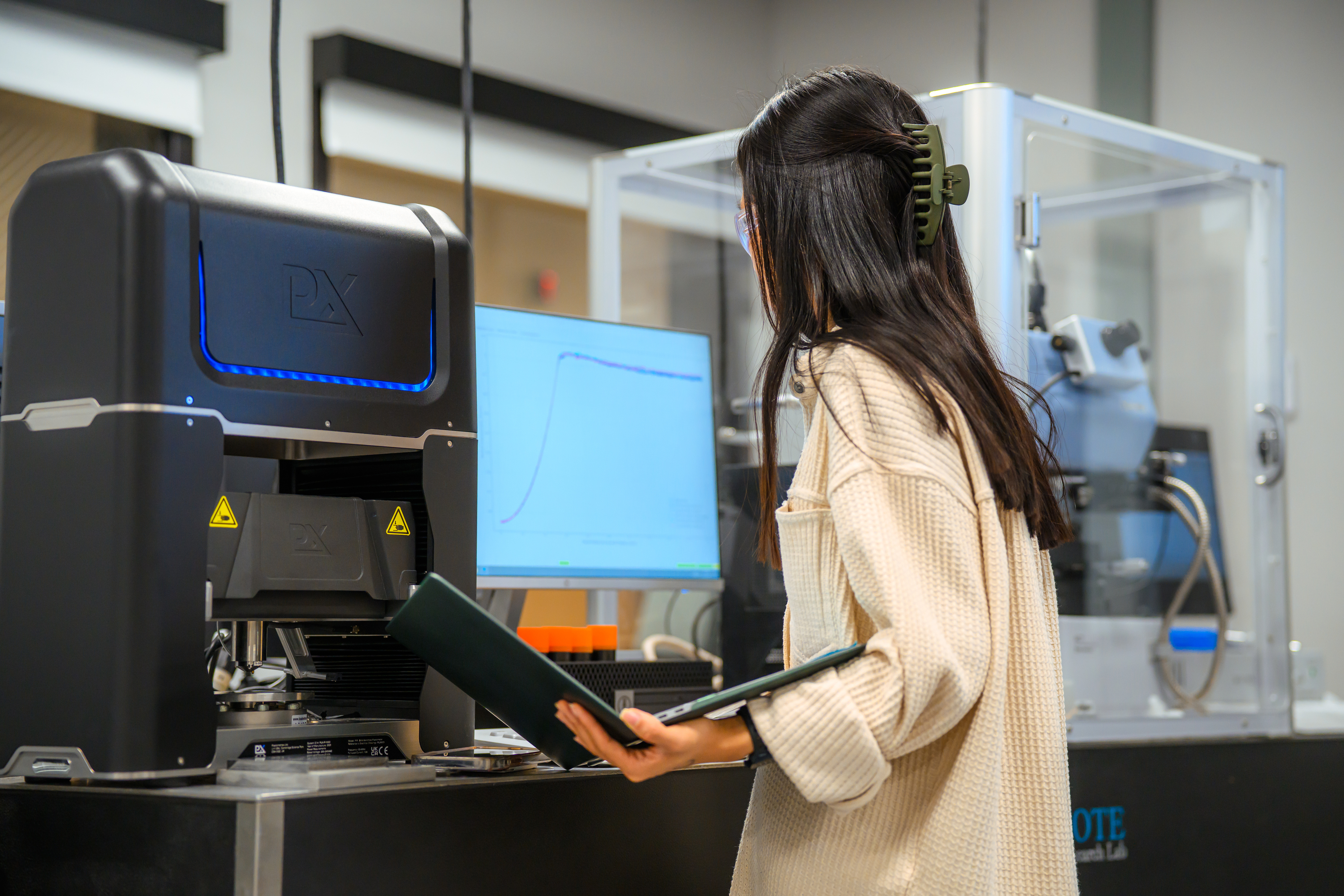
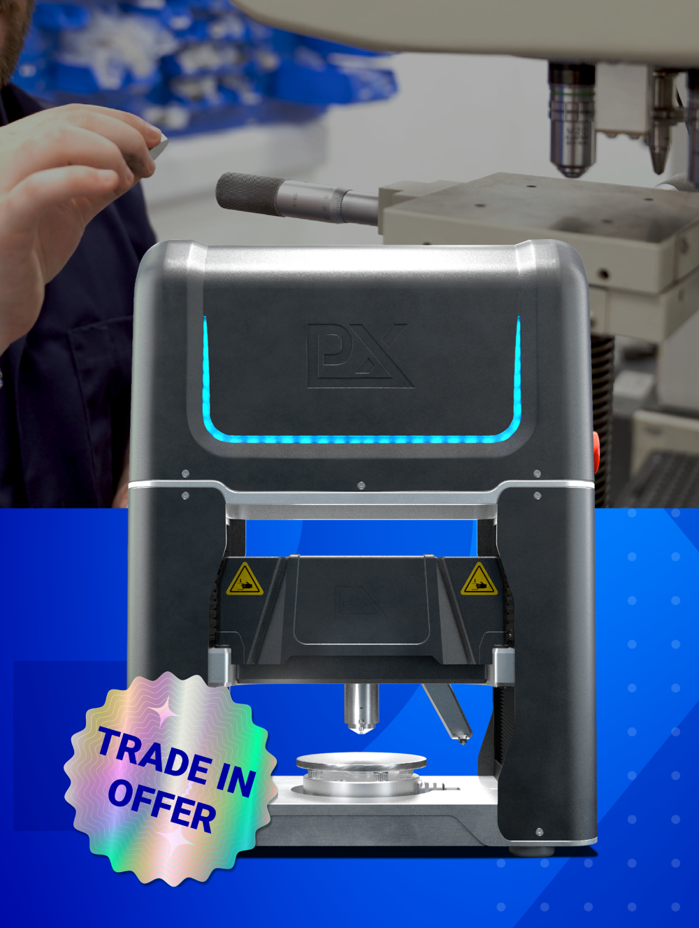
The PLX-AutoStage is a new module for the PLX-Benchtop that automates PIP testing across multiple samples and indent locations. It delivers precise data collection at 0.15 mm placement accuracy, spatially resolved property maps at 1.5 mm indent spacing, and unattended operation that returns days of engineer time to higher-value work
Mechanical testing has a workflow problem. The two methods most relied-on by engineers, tensile testing and hardness testing, each carry notable trade-offs. Tensile testing produces defensible, trusted data, which is why it’s understood to be the gold standard, but tests are both time and resource heavy. Hardness testing is substantially faster, but it doesn’t measure a stress-strain response and any link to strength relies on empirical correlations. There’s undeniable friction between these methods and the kind of work R&D and QA teams are now routinely doing: characterising more samples, mapping more features, iterating faster, and producing large volumes of data within small windows of time. When the choice is between reliable data and speed, it’s no wonder that operations suffer.
The PLX-AutoStage was designed to relieve the pressure on the testing pipeline. This new module for the PLX-Benchtop turns a single, hands-on test into an automated, multi-sample, spatially resolved workflow. Using Profilometry-based Indentation Plastometry (PIP testing), an ASTM-standardised method for determining the mechanical properties of metals, the device produces tensile-equivalent stress-strain data non-destructively. PIP testing has already been adopted across organisations including NASA, Airbus, Renishaw, Leonardo, NPL, and Nikon AM Synergy. What follows will walk through the three things the PLX-AutoStage was built to deliver, and what each unlocks for high-throughput characterisation programmes.
Target Any Feature and Collect Real Stress-Strain Data
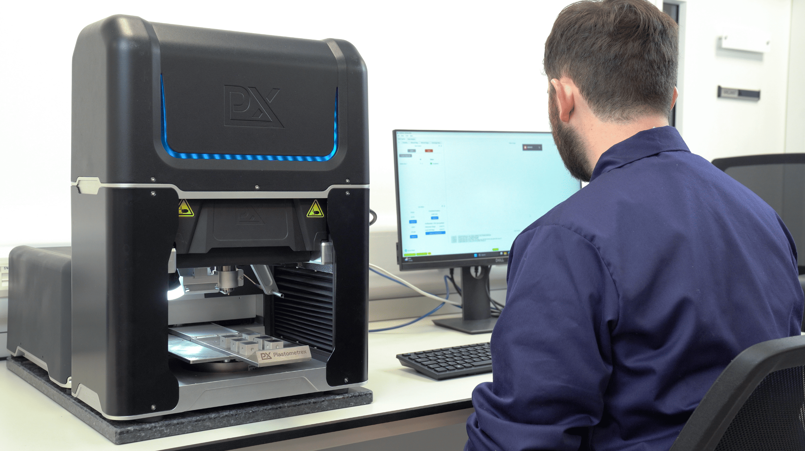
Conventional mechanical testing methods leave a lot on the table. Not only is tensile testing slow, taking hours if not weeks, but each test only provides a single bulk average. If, for example, an engineer wants to measure mechanical properties from three separate areas of a complex additively manufactured component, tensile testing can act as a roadblock. Not only would three separate tensile specimens be required, but it may not even be possible to extract test pieces from the specific features that the engineer may be trying to characterise. This may require building additional samples, where build conditions may be quite different from the actual regions of interest. This means that he or she may spend a substantial amount of time and money to gather data that isn’t representative of that complex part.
This is often where hardness testing comes in. However, while it can sample locally and perform tests quickly, this comes at the sake of certainty. The numbers returned by hardness testing are conditional on the test setup: variables such as load, indenter, dwell, and the material’s surface can impact results. Further, translating hardness data to mechanical strength properties relies on conversions and proxies that carry their own uncertainty. Returning to the previous example of the complex AM part, while hardness testing could be used to directly gather data from each of the three locations on the component, the engineer would still need to rely on weak empirical correlations. This would leave the data a step removed from the property the design decision actually depends on.
With the PLX-AutoStage, users can confidently collect data directly from precise locations on components. Image-based targeting within the software allows engineers to select exactly where they would like to test, such as the centre of a weld bead, a single layer in a cross section, or the same point on every sample in a batch. No matter the sample type, every indent lands within 0.15 mm of the location selected on screen. Each test returns yield strength, ultimate tensile strength (UTS), and the full work-hardening response: the same data generated by a tensile pull, but without any conversions or proxies.
When every indent lands exactly where intended, batch-to-batch comparisons carry weight. The same engineer who may have struggled to gather data using tensile or hardness testing can quickly and easily gather representative data across complex samples or screen dozens of new alloys in minutes, not hours or weeks. And because PIP testing provides tensile-equivalent data, users can trust the test outputs when making key engineering decisions.
Build Full Property Maps From a Single Sample
As manufacturing has gotten more advanced, variations in mechanical properties throughout components can arise. Welds, heat-affected zones, additive build directions, rolled-product through-thickness gradients, and thickness changes in cast or forged parts all shift mechanical behaviour across a single component. Conventional testing methods haven’t kept up with advanced manufacturing techniques, especially when it comes to resolving the variations present in complex components.
As discussed above, tensile testing provides a single bulk average per coupon pulled. This number is not tied to any specific location in the part the tensile coupon is meant to represent, making it virtually useless for property mapping at this length scale. Hardness mapping, while able to capture relative variation, requires conversions before the data gather can describe fundamental material properties. Even after these conversions, the data produced is still an estimate and therefore not entirely reliable. The map and the property always remain a step apart, which can impact the utility of the data.
With spatially resolved stress-strain data, however, the picture starts to look different. An engineer working with feature-level information can make design decisions based on local properties, rather than using a bulk average that may or may not apply. Process parameters can be validated against the local outputs they produce, point by point. And the heat-affected zone of a weld can be characterised directly, including its yield strength, UTS, and work-hardening response, on the same sample as the parent material.
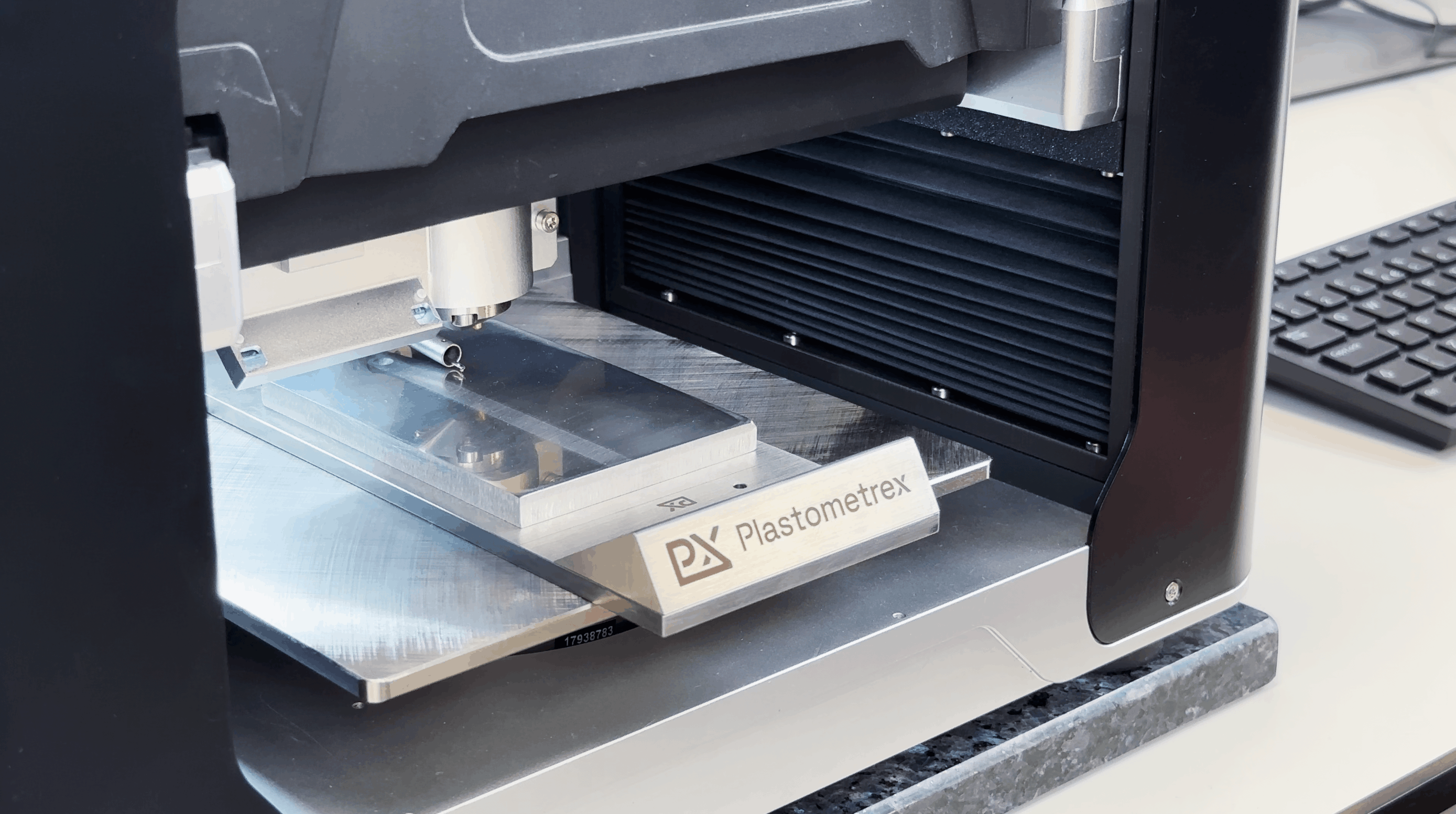
The PLX-AutoStage was designed to make this kind of work practical. Indent spacing can be set as close as 1.5 mm apart, which is fine enough for resolved mapping across many welds, HAZs, and complex part features. Indent locations are programmed into a grid or a custom set of positions in the software, and from that point the AutoStage executes the array indent by indent without further operator intervention. Each location returns yield strength, UTS, and the full work-hardening behaviour, so the output is a property map rather than a single bulk number.
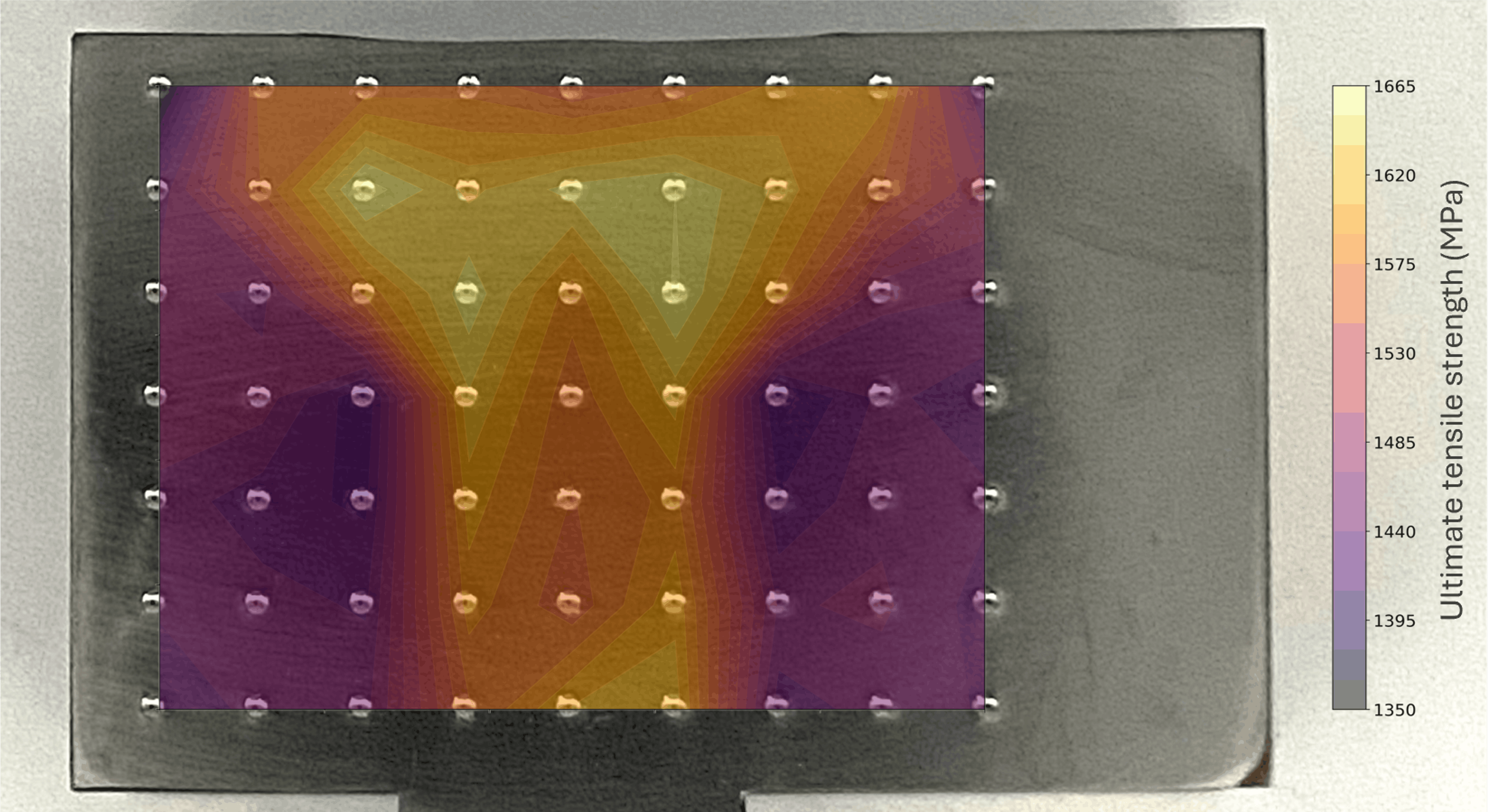
One representative example is a titanium weld mapped using a 7 × 9 grid, totalling 63 indents across the parent material, the weld zone, and the surrounding HAZ (Figure 1). The resulting map reveals mechanical variation across all three regions on a single sample, and individual stress-strain curves can then be extracted at any location of interest to compare weld and parent material behaviour directly. This is something that neither conventional tensile testing nor hardness mapping can deliver from a single specimen.
This capability has resonated strongly with users working on complex weldments. As Michael Benoit, Assistant Professor at the University of Waterloo, has put it: “We found PIP testing to be incredibly useful to assess the mechanical properties of weld fusion zones, made using custom, limited supply filler wires, in our recent work.”
Run Unattended Batches and Reclaim Engineer Hours
Getting fundamental material properties has always been hands-on work. Each tensile pull requires an operator to load the coupon, run the test, and record the result. And while automated hardness systems can run at volume, hardness returns a proxy for strength rather than the stress-strain data engineers need to defend design decisions. At the scale of a serious R&D or QA programme, this adds up. Days of engineering time per week, in some cases more, are absorbed by tensile test execution alone.
That time is rarely itemised in any programme budget, but it shows up in the work that doesn’t get done. Engineers spend less time on data analysis, parameter optimisation, and the higher-value problem-solving they are best placed to do, because they spend more time setting up and running tests. Programmes ship fewer data points than they would have liked, decisions get made on thinner evidence, and iteration slows.
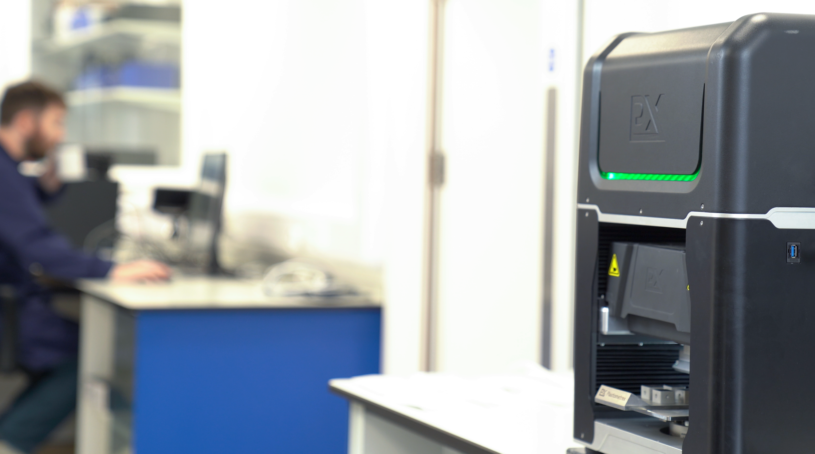
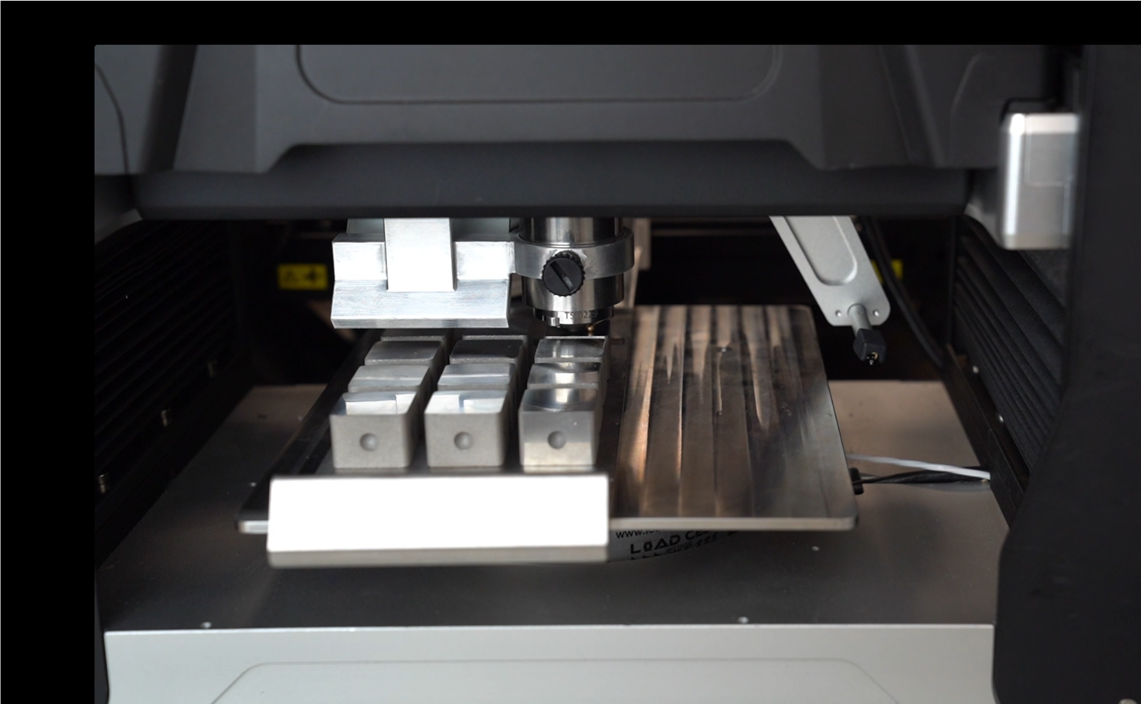
The PLX-AutoStage was built with this very challenge in mind. Multiple samples can be loaded onto the AutoStage tray in a single setup, indent locations defined once across all of them, and the test programme started with a single click. From that point on, the system moves between samples and indents automatically. Engineers can step away and return to a finished run, with stress-strain curves already filed in the software ready for review.
A recent QA-focused example illustrates the practical value of this. Twelve titanium samples from different production runs were loaded onto a single AutoStage tray and tested in one automated sequence (Figure 2). The resulting data set, returned without operator intervention between samples, identified one sample with a yield strength more than two standard deviations from the mean of the batch, flagging it as out of specification quickly and unambiguously. The kind of screening exercise that would previously have leaned on hardness as a proxy can now be run directly on the strength data engineers care about, with the engineer’s time freed up for everything else.
Conclusion
For high-volume mechanical characterisation, engineering teams have long had to navigate a hard trade-off between defensible data and practical throughput. The PLX-AutoStage was designed to take that compromise off the table.
In practice, this means three things. Confident data collection at every indent, with 0.15 mm placement accuracy and full stress-strain output rather than hardness proxies. Spatially resolved property maps at 1.5 mm indent spacing across welds, HAZs, additive builds, and complex parts. And the return of days of engineer time previously absorbed by hands-on test execution, freed for the analysis, optimisation, and design work that engineering teams are there to do.
What hasn’t changed is the engineer’s role. The decisions about where data should be collected, which features matter, and how the resulting information feeds into a design or qualification programme remain human decisions. The PLX-AutoStage handles the execution. The engineer keeps the judgement.
To learn more about the PLX-AutoStage, click here.
FAQ
Does the PLX-AutoStage work with my existing PLX-Benchtop?
Yes. The PLX-AutoStage is a modular add-on that slots into your existing PLX-Benchtop. Once fitted, you can switch between manual PIP testing and fully automated multi-sample runs on the same instrument, using the same CORSICA software.
What materials can the PLX-AutoStage test?
The PLX-AutoStage can test the same range of metals as the PLX-Benchtop, including steels, titanium alloys, nickel superalloys, aluminium alloys, and copper alloys. Any material compatible with PIP testing is compatible with the PLX-AutoStage.
How many samples can the PLX-AutoStage handle in a single run?
The AutoStage tray accommodates samples across an 80 x 125 mm footprint. Depending on sample size, that ranges from tens of large samples to hundreds of small ones in a single unattended run. Trays can be reloaded to run continuous batches across longer campaigns.
Is the PLX-AutoStage backed by an international testing standard?
Yes. The PLX-AutoStage uses PIP testing (Profilometry-based Indentation Plastometry), formalised in ASTM E3499-25. PIP-derived values have been benchmarked against tensile testing to within a MAPE of 4% across hundreds of samples spanning aluminium, steel, nickel, and other alloy families.

James has an undergraduate degree in Natural Sciences from the University of Cambridge (2019). In 2019 he joined the Rolls-Royce UTC Group under the supervision of Professor Cathie Rae and completed a PhD focusing on the deformation behaviour of single crystal Ni-based superalloys. Since joining Plastometrex in 2024, James has worked on validation of the Indentation Plastometry technique across a wide range of materials, continuing to improve the reliability and accuracy of Plastometrex’s SEMPID software packages, as well as developing new product features.