Most metallic samples fail in a way governed entirely by their plasticity, with rupture occurring once peak plastic strain in the neck reaches around 50 to 100%. Brittle materials behave differently, fracturing at a stress set by the Griffith energy criterion and by the size of the largest flaw, and this guide works through the strain energy release rate, the crack resistance Gc, and why the criterion cannot simply be transferred to ductile metals. It closes on the practical caveat for indentation plastometry: very hard metals and samples containing pores or cracks can fracture before a neck forms, and an indentation test gives no warning of that.
The behaviour of most metallic samples during mechanical testing (to “failure”) is dominated throughout by their plasticity characteristics. Not only do they control the onset and development of uniform plastic deformation, but they also dictate when necking will start and how the neck will develop. In fact, even the final rupture event is often predictable on the basis of it occurring when the peak true plastic strain (in the neck)reaches a critical value. However, “brittle” materials do not behave like this during tensile testing. They tend to undergo rapid fracture, often with little or no prior plastic deformation. Their apparent “tensile strength” (UTS value)depends on their toughness, and also on the presence and size of cracks or other flaws (such as pores) in the sample concerned. Such behaviour is not common with metals, but something similar (i.e. fracture before a neck starts to form) can occur in metallic samples - particularly if they are very hard(commonly associated with low toughness) and/or contain substantial flaws of some sort. The outcome of an indentation test provides no information about this possibility.
Plasticity-Dominated Tests
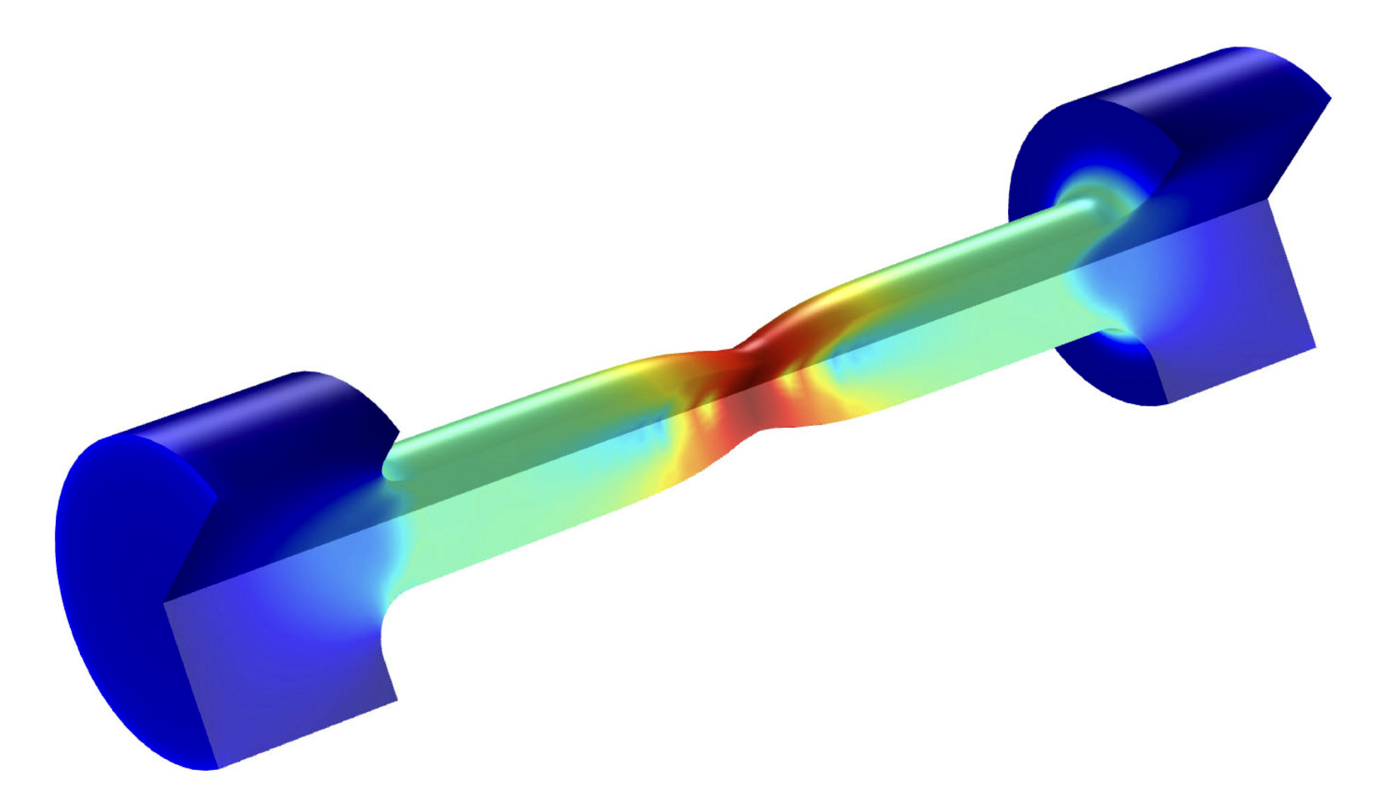
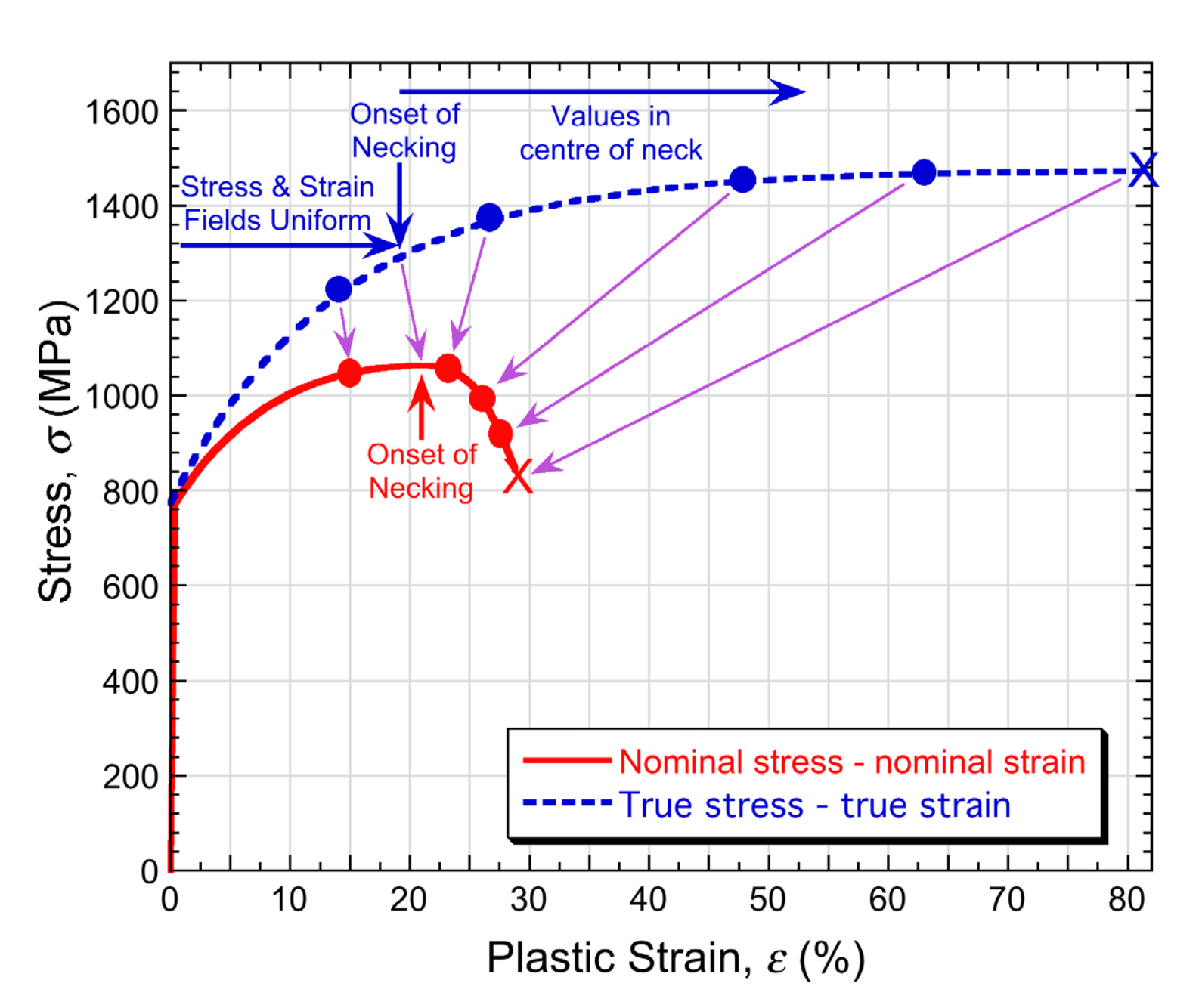
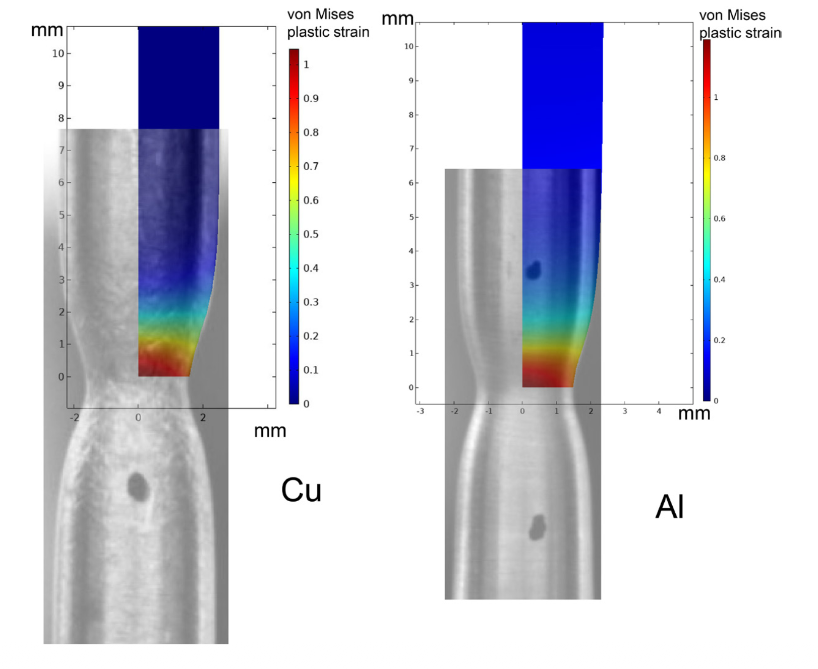
Most tensile tests on metallic samples proceed as indicated in Fig.1. There is always some uncertainty about the final rupture event, but it usually occurs when the peak plastic strains in the neck have reached high values (~50-100%), at which point the dislocation density is high and the material is no longer able to respond plastically. The toughness of the original unstrained material is not really relevant to this final rupture event.
Fracture-Dominated Tests
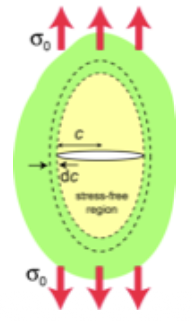
With a brittle material, on the other hand, tensile testing is likely to give an approximately linear stress-strain plot, followed by fracture (at a stress that is affected by the presence and size off laws). For an ideally brittle material, a simple (Griffith) energy-based criterion for fast (unstable) crack growth [1] is applicable. The energy released during crack advance comes from stored elastic strain in the surrounding material (plus any work done by the loading system). As a crack gets longer, the volume of stress-free material “shielded” by it from the applied stress increases - see Fig.2. The driving force for crack propagation therefore increases. The strain energy stored per unit volume in (elastically) stressed material is given by:
U = ½ σ0 ε0 = σ0² / 2E
so the energy released when the crack extends(at both ends) by dc is the product of this expression and the increase in stress-free volume. The shape of the stress-free region is not well-defined, and the stress was in any event not uniform within it before crack advance, but taking the relieved area to be twice that of the circle having the crack as diameter gives a fair approximation. Thus, for a plate of thickness, the energy released during incremental crack advance is given by:
dW = (σ0² / 2E) 2(2πc t dc) = 2σ0² πct dc / E
A central concept in fracture mechanics is that of stored elastic strain energy being released as the crack advances. The strain energy release rate (crack driving force) is usually given the symbol G.It is a “rate” with respect to the creation of new crack area (and so has units of J m-2) and does not relate to time in any way. It follows that:
G = dW / new crack area = 2σ0² (πct dc / E) /(2t dc) = π (σ0² c / E)
The value of the constant (pi in this case) is not well defined. It depends on specimen geometry, crack shape/orientation and loading conditions. In any event, the approximation used for the stress-free volume is simplistic. However, the dependence of G on (σ²c/E) is more general and has important consequences, particularly in terms of the linear dependence on crack length.
In order for crack propagation to be energetically favoured, the strain energy release rate must be greater than or equal to the rate of energy absorption, expressed as energy per unit(projected) area of crack. This energy requirement is sometimes known as theGriffith criterion. Focussing now on an edge (surface) crack of length c, propagating inwards, for a brittle material this fracture energy is simply given by 2γ (where γ is the surface energy, with the factor of 2 arising because there are two new surfaces created when a crack forms). It can be considered as a critical strain energy release rate, Gc. It is a material property. It is sometimes termed the crack resistance. The fracture strength can thus be expressed as follows
G ≥ Gc = 2γ
∴ π (σ0² c / E) ≥ 2γ
∴ σ* = (2γE / πc)^½
This equation can be used to predict the stress at which fracture will occur, for a component containing a crack of known size. However, it relates only to materials for which the fracture energy is given by 2γ - ie for which the energy absorbed during crack propagation is only that needed to create the new surface area. It may be noted at this point that the magnitude of 2γ does not vary very much between different materials and is always relatively low - usually <~10 J m-2. These are regarded as “ideally brittle” materials. Some materials, including many glasses, do behave at least approximately in this way, but most materials do not.
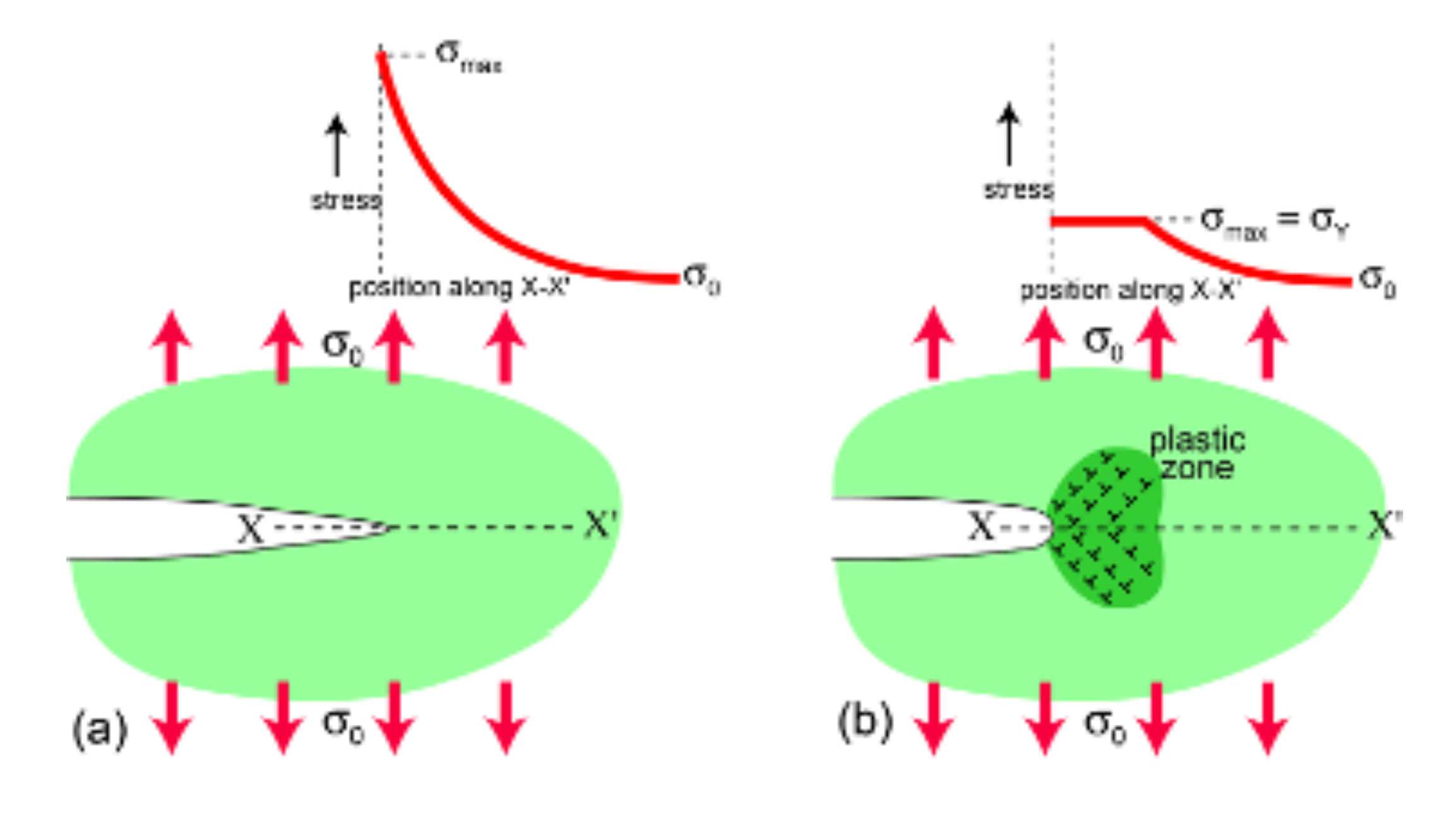
It has long been clear that the simpleGriffith condition (Eqn.(3)) applies only to brittle materials. For metals, a fracture event, often preceded by extensive plastic flow throughout the sample, and then by localised necking, is usually very different from that in brittle materials. Apart from the possibility of energy being (permanently) absorbed by uniform plasticity before any crack growth occurs, the crack propagation process itself requires much more energy than in brittle materials. There tends to be a zone of plasticity ahead of the crack tip, irrespective of whether there has been much plastic deformation prior to the onset of fracture. Fig.3shows how this plasticity raises the radius of curvature, r, at the crack tip and reduces the stress concentration effect. (The peak stress, indicated as σYin Fig.3(b), is nominally the yield stress, although it will be higher than this if work hardening occurs.)
The work done during plastic deformation must be supplied by the crack driving force (release of elastic strain energy). It might be imagined that a simple modification could be made to Eqn.(4),replacing 2γ by an alternative version of Gc, which takes account of these extra energy requirements (and, indeed, Gc values for tough materials such as metals are commonly greater than 2γ by several orders of magnitude). This would allow the Griffith criterion to be applied to ductile materials, but this must be approached with considerable caution. It would suggest that ductile materials should be as sensitive to the presence of flaws as brittle materials, although they would have higher fracture stresses for a given crack size. In fact, failure stresses are not dramatically or systematically higher for ductile materials, although they certainly fracture less readily and require much more energy input. Furthermore, ductile materials show little or no sensitivity to initial flaw size. Very ductile materials can fail by ductile rupture (progressive necking down to a point), with little or no crack propagation as such. Failure in such cases is dominated by plastic flow and Eqn.(4) is of no relevance. Of course, such highly ductile materials are too soft to be useful for most purposes and failure of engineering metals does usually involve a fracture event, often after both uniform plastic flow and necking have occurred. However, even in this case, Eqn.(4) is not really of much use. The appropriate fracture energy value would relate to material that had already undergone extensive plastic deformation and the stress would be the true value acting in the neck. Neither of these are well-defined. In practice, it is common to simply assume that final fracture will occur when the plastic strain in the neck reaches a critical value, and indeed this is often a plausible assumption, although the critical strain certainly cannot be defined universally.
A Final Caveat
The division of materials into “brittle” and“ductile” types is in general valid, with most metals falling into the latter category. They're thus well-suited to characterisation via indentation, focussed entirely on the plastic response. However, some (usually very hard)metals might fracture at relatively low strains, and in particular at strains below that at which a neck would be predicted to form – which might be as high as several tens of %. They will then exhibit a UTS that is lower than the one at which a neck would develop (as predicted using indentation plastometry data).On the other hand, the onset of yielding should still be close to that obtained via indentation.
A final point to make is that “premature”fracture of this type (ie fracture without necking) might even be observed in a metal that is not very “strong” or “hard”, if the sample contains significant flaws. Even a metal that is nominally quite ductile can fracture prematurely if the sample contains a large crack or other flaw (such as a pore). This is not uncommon in certain types of product, such as castings and, potentially at least, in material made by additive manufacturing (which has some features in common with casting). Of course, such flaws are usually undesirable, but they may nevertheless be there. In fact, a further point can be made about highly porous material, which is that they are in any event unsuited to indentation plastometry, both because large pores in the vicinity of an indent may distort the indent profile and because finer, dispersed porosity will mean that the plastic deformation will involve a volume change – the absence of which is an underlying assumption of most FEM modelling.
References
1. Griffith, A.A., The Phenomena of Ruptureand Flow in Solids. Phil. Trans. Royal Society, 1920. A 221: p. 163-198.
2. Clyne, T.W. and D. Hull, An Introduction toComposite Materials. 3rd ed. 2019, Cambridge: Cambridge University Press.
Frequently Asked Questions
What controls failure in a normal tensile test on a metal?
Plasticity characteristics dominate throughout, governing the onset and development of uniform deformation and dictating when necking starts and how the neck develops. Final rupture usually occurs once peak plastic strains in the neck reach high values of around 50 to 100%, at which point dislocation density is high and the material can no longer respond plastically. The toughness of the original unstrained material is not really relevant to this rupture event.
What is premature fracture?
It is fracture occurring before a neck starts to form, which brittle materials undergo routinely with little or no prior plastic deformation. Something similar can happen in metallic samples, particularly very hard ones, where low toughness is commonly associated, or samples containing substantial flaws.
What is the Griffith criterion?
It is an energy-based criterion for fast, unstable crack growth in an ideally brittle material. Crack propagation is energetically favoured when the strain energy release rate is greater than or equal to the rate of energy absorption, expressed as energy per unit projected area of crack. As a crack lengthens, the volume of stress-free material shielded from the applied stress increases, so the driving force for propagation rises.
What is the strain energy release rate?
Usually given the symbol G, it is the stored elastic strain energy released as the crack advances. It is a rate with respect to the creation of new crack area, with units of J m-2, and does not relate to time in any way. The dependence of G on σ²c/E matters more than the exact constant, particularly the linear dependence on crack length.
What is Gc?
Gc is the critical strain energy release rate, a material property sometimes termed the crack resistance. For a brittle material with an edge crack, the fracture energy is simply 2γ, where γ is the surface energy, the factor of two arising because two new surfaces are created when a crack forms.
Which materials are genuinely "ideally brittle"?
Those for which the energy absorbed during crack propagation is only that needed to create the new surface area. The magnitude of 2γ does not vary much between materials and is always relatively low, usually below about 10 J m-2. Many glasses behave at least approximately this way, though most materials do not.
Can the Griffith criterion be applied to ductile metals?
Only with considerable caution. Replacing 2γ with a version of Gc that accounts for the extra energy is tempting, and Gc for tough metals is commonly several orders of magnitude greater than 2γ, but doing so implies that ductile materials should be as flaw-sensitive as brittle ones. In practice, failure stresses are not dramatically or systematically higher for ductile materials, and they show little or no sensitivity to initial flaw size.
Why does plasticity change crack behaviour in metals?
A zone of plasticity tends to form ahead of the crack tip, whether or not much plastic deformation preceded the onset of fracture. This raises the radius of curvature at the tip and reduces the stress concentration effect. Crack propagation itself therefore requires much more energy than in brittle materials, on top of any energy permanently absorbed by uniform plasticity beforehand.
How is final fracture usually predicted in practice?
By assuming it occurs when the plastic strain in the neck reaches a critical value, which is often a plausible assumption. Applying the Griffith relation is of little use here, since the appropriate fracture energy would relate to material that had already undergone extensive plastic deformation and the stress would be the true value in the neck, neither of which is well-defined. The critical strain cannot be defined universally.
What does this mean for indentation plastometry?
Most metals are ductile and therefore well-suited to characterisation via indentation, focussed entirely on the plastic response. Some very hard metals may fracture at strains below the point where a neck would be predicted to form, giving a UTS lower than the value predicted from indentation data, though the onset of yielding should still be close. An indentation test provides no information about whether premature fracture will occur.
Why is porous material unsuited to indentation plastometry?
Large pores near an indent may distort the indent profile. Finer, dispersed porosity means the plastic deformation involves a volume change, and the absence of such a change is an underlying assumption of most FEM modelling. Flaws of this kind are not uncommon in castings and, potentially, in material made by additive manufacturing.

Bill was Chief Scientific Officer atPlastometrex (now retired) and Emeritus Fellow in the Mechanics of Materials atthe University of Cambridge, where he served as Professor of the Mechanics ofMaterials. A Fellow of the Royal Academy of Engineering, his research spans thethermo-mechanical behaviour of composites and surface coatings, with a focus onprocess simulation and numerical modelling of material performance. His work onindentation techniques and residual stress measurement underpins much of thePIP methodology now commercialised by Plastometrex.